I bought a 3D printer, and, as a result, got into 3D modeling recently. I'm still super new to everything. From experience, this means I should write down things I'm learning. The beginner's perspective is valuable to other beginners!
A squircle is a square who's corners are replaced by curves with g3 continuity, which can be thought of as really hecking smooth curves where the derivatives of the curve must also be smooth. In FreeCAD 1.0.x, it's not immediately obvious how to sketch such a shape, in order to create solid shapes out of it. With the help of ChatGPT, and the internet, I figured out a somewhat cohesive way to do this recently. Now I need to write it down lest I forget!
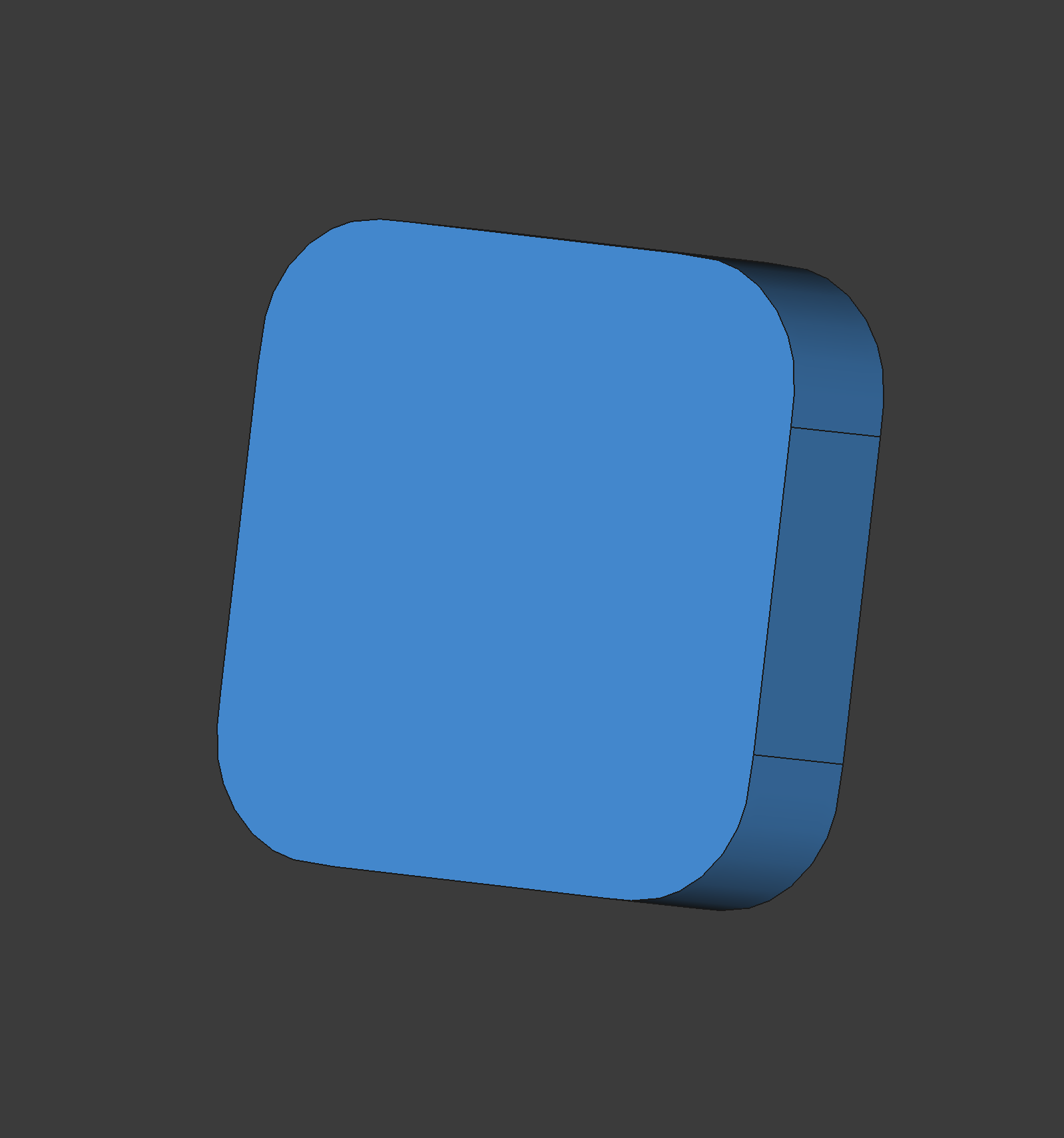
Our goal is to have a sketch of a squircle that we can use to pad or pocket to create 3D shapes. In the sketch, we want to first create the sides of the square that's straight, and connect them with the g3 curve, which can be done via the Curves workbench.
But first, let's break down the squircle's geometry a bit. A squircel is both a square and a circle. Each side of the square has a straight line, it ends at a specific point, let's call it A, where the curve of the circle begins. From this point, if you draw a line perpendicluar to the straight part, and repeatly draw it on every such point, the new lines will intercect at point B. The length of the line AB is the radius of the squircle.
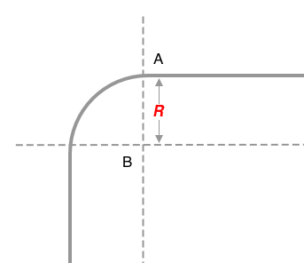
In FreeCAD, we want to include these AB lines as guides. They will define both the straight lines on the side, as well as the correct space for the curves. The guide lines and the sides will form a cross shape. Make sure everything is symmetrical, and the AB lines all have the same size.
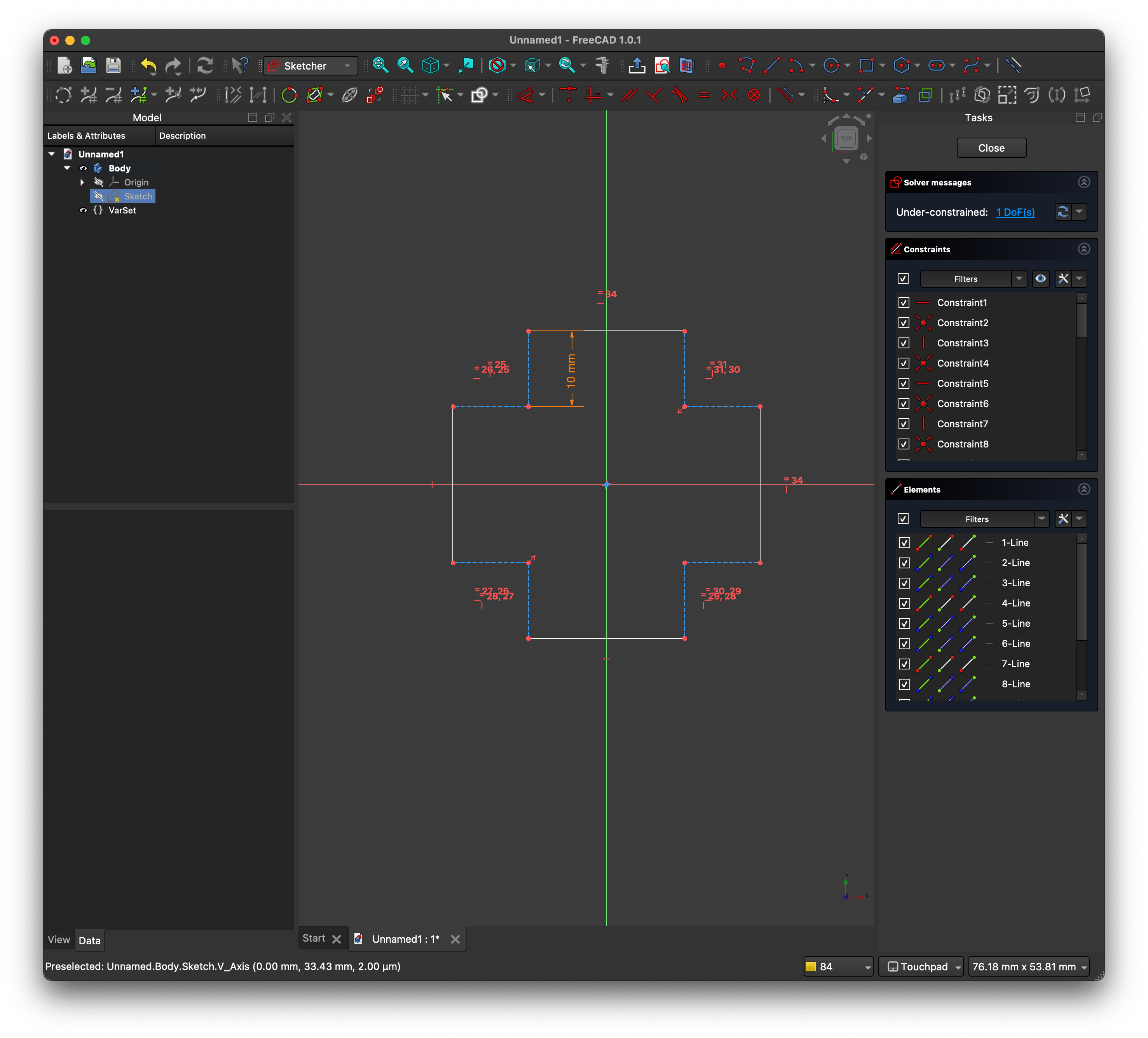
Note that the AB lines are in construction mode represented by dashes.
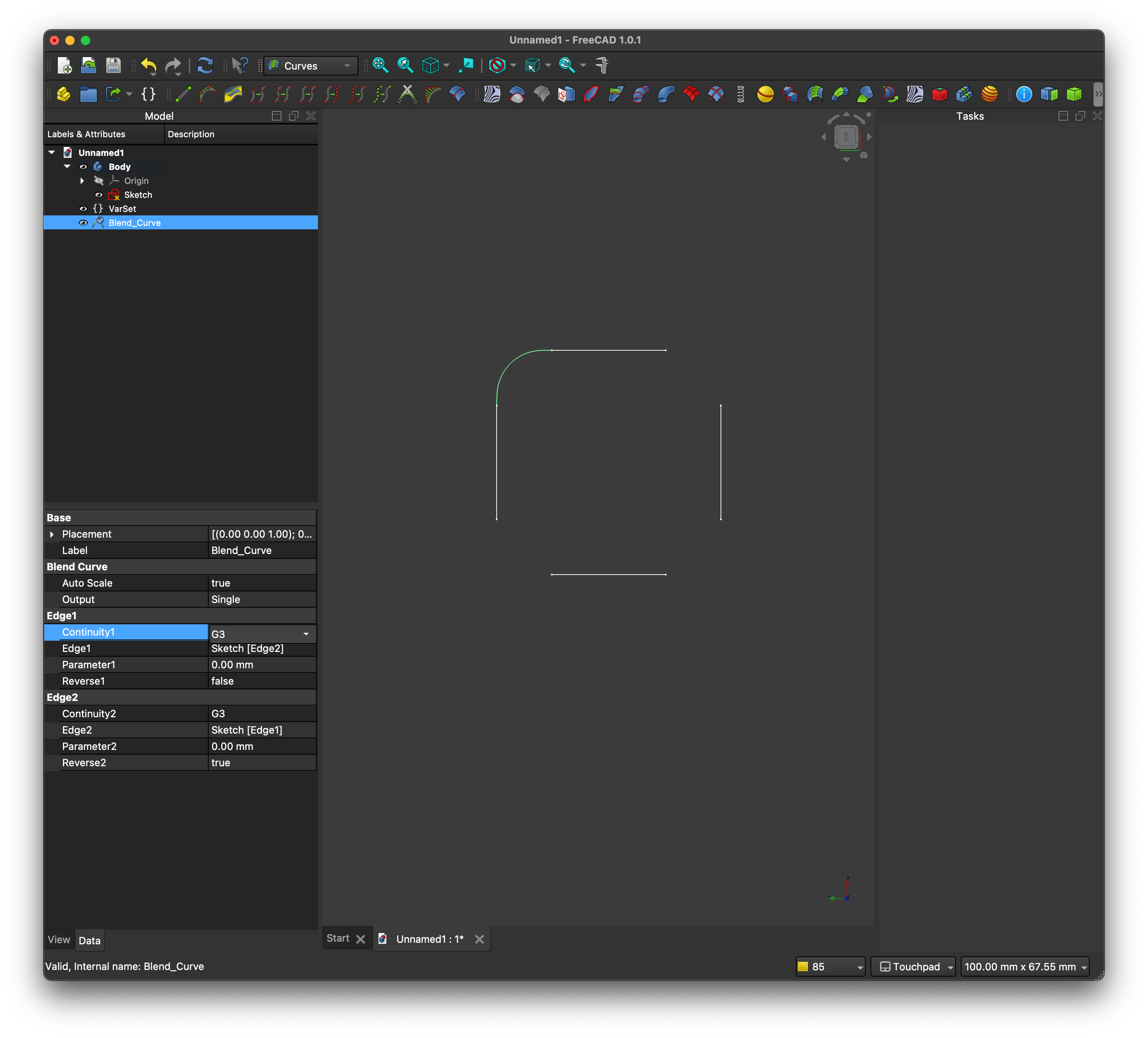
Exit the Sketch. Switch to the Curves workbench, and select 2 of the 4 concrete edges from the sketch. Use the Blend Curve option from the workbench. And you'll get some funky looking curves connecting the straight lines, and it's represented by a "Blend_Curve" in the object tree.
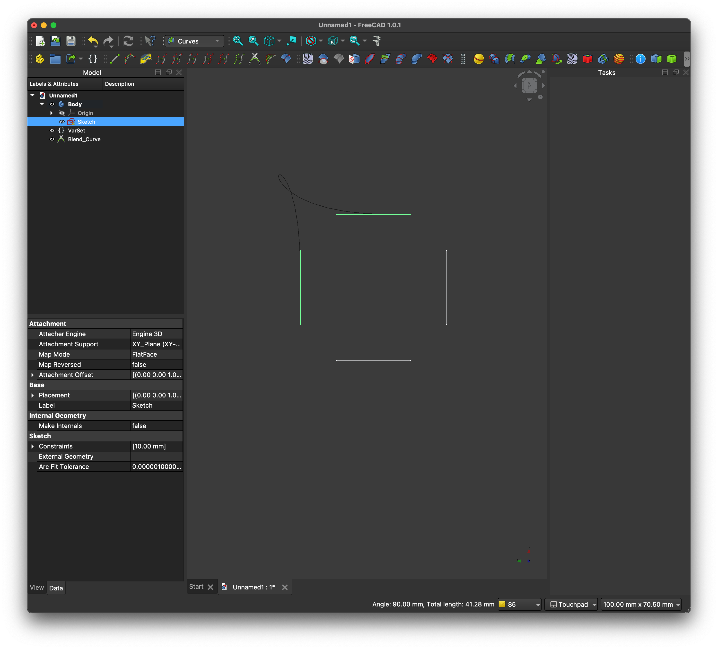
Select the "Blend_Curve" in the tree and tweak its Data fields.
- Set
Auto Scaletotrue. - Set
Parameterto0mmfor both edges. - The new curve should smoothely connect with the ends of the sides that's close to the other straight side. If not, set
Reversetotrue. - Most importantly, set
Continuityfor both edges toG3.
That completes 1 of the 4 corners. Repeat for the other 3. And now you have a 2D squircle!
There should be 4 "Blend_Curve"s in the object tree, as well as the original sketch.
Now things get a little convoluted. Although things on screen look like a closed wire, we can't use it to create a 3D shape for 2 reasons:
- the "Blend_Curve"s aren't part of any body.
- the curves and the straights don't belong to the same geometry.
There's a easy way to fix both problems, thanks to the fact that multiple shapes in FreeCAD 1.0 can comine into a single sub-objects shape binder.
Switch back to the Part Design workbench. Activate the body you want the final 3D shape in (can be an existing or new body). Select all 4 blend curves in the object tree, and the sketch. You should see the entire wire highlighted in a uniform color. Then use the sub-objects shape binder tool, which gets you a single binder in the tree of the active body.
You should see the binder on screen. Hide other things if they are distracting you. Now, select the edges in the binder -- all 8 of them! After that, you can use the Pad tool to create a 3D shape. And that's it!
Obviously, a squircle is the simpliest shape to incorporate a g3 continous curve. But once we have the curve as a wire, anything is possible in FreeCAD.